Home Blog Fire protection systems
Fire protection systemsHow to Calculate Fire Water Tank Capacity
Learn how to calculate fire water tank capacity from hydraulic demand, required duration and usable volume using NFPA 22, NFPA 13 and NFPA 14 principles.
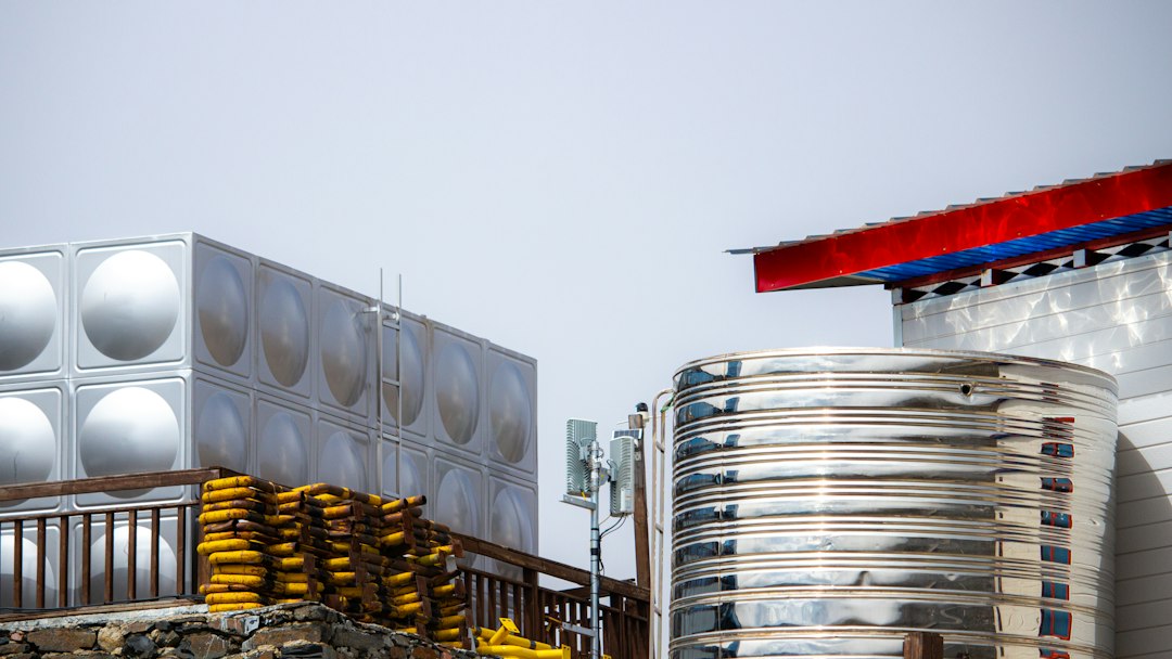
Fire water tank capacity is not a fixed number based only on building area. The correct tank volume comes from the governing fire protection demand multiplied by the required water-supply duration, with any simultaneous hose or standpipe demand included where the applicable design standard requires it.
This guide shows a practical workflow for sizing a dedicated fire water tank for sprinkler and standpipe systems and explains the role of NFPA 22, NFPA 13 and NFPA 14.
Which NFPA standard determines the tank size?
NFPA 22 governs the construction, arrangement and protection of water tanks used for private fire protection. It does not replace the hydraulic design standard that establishes how much water the protected system needs.
For sprinkler systems, the required flow and duration are established by the applicable criteria in NFPA 13. For standpipe systems, the required water supply is established by NFPA 14. A combined sprinkler/standpipe project therefore has to be evaluated as a system, not by applying a generic “X gallons per square metre” rule.
The basic tank-sizing equation
For a dedicated tank where the tank is the water source for the full design demand, the basic engineering relationship is:
Required usable water volume = governing design flow × required duration.
For US units:
Volume (gal) = Flow (gpm) × Duration (min).
For metric units:
Volume (m³) = Flow (L/min) × Duration (min) ÷ 1,000.
The important words are governing design flow and required duration. Both must come from the applicable system design criteria.
Step 1: Establish the sprinkler hydraulic demand
Use the approved hydraulic calculation to determine the sprinkler demand at the water-supply point. Where the design criteria require a hose-stream allowance, that allowance must also be included in the total water-supply demand.
Do not estimate the sprinkler flow from the number of sprinklers in the entire building. Hydraulic design is based on the applicable design area and occupancy/storage criteria.
Step 2: Check standpipe demand
If the building has an automatic or semiautomatic standpipe system, review the NFPA 14 demand and duration applicable to the project. NFPA material for standpipe systems identifies a minimum 30-minute water-supply requirement in the relevant automatic/semiautomatic provisions.
Where sprinkler and standpipe systems share the same tank and pump, the designer must determine the combined demand required by the applicable rules rather than simply sizing each system separately and adding two complete tank volumes.
Step 3: Apply the correct duration
Water-supply duration is not always the same. NFPA 13 design criteria can require different durations depending on the occupancy, commodity, storage arrangement and sprinkler design approach. Published NFPA material includes storage examples with 60-, 90-, 120- and even 180-minute durations.
That is why a statement such as “every sprinkler tank needs 60 minutes” can be wrong. The project-specific design criteria must be checked.
Worked example
Assume the governing sprinkler calculation requires 750 gpm, including the applicable hose allowance, for a required duration of 60 minutes.
The usable water volume is:
750 × 60 = 45,000 gal.
Converting to cubic metres:
45,000 × 3.785 ÷ 1,000 ≈ 170.3 m³.
The design would therefore need at least about 170 m³ of usable fire water for this demand, before resolving tank geometry, unusable level, suction arrangement and any project/AHJ allowances.
SESCO Engineering Note: the nominal geometric capacity of a tank is not automatically the same as its usable fire-water capacity. The low-water level, suction connection, anti-vortex arrangement and required operating levels can leave part of the physical tank volume unavailable to the fire pump.
What if there is a reliable city-water supply?
If an approved external water supply is permitted to contribute to the fire demand, the required stored volume can be affected by the approved design arrangement. This must be demonstrated with reliable supply data and accepted by the authority having jurisdiction. Do not reduce tank volume based only on a single static-pressure reading.
Usable volume vs nominal tank volume
After calculating the required usable volume, the physical tank must be configured so that this amount of water is actually available to the fire protection system. The design should consider:
- minimum operating water level;
- pump suction connection and anti-vortex requirements;
- overflow and freeboard arrangements;
- tank compartments where required by the project;
- refill arrangement and reliability;
- access, drainage, inspection and maintenance;
- structural loads and foundations; and
- freeze, heat, corrosion and water-quality conditions applicable to the site.
Common fire water tank sizing mistakes
- Using building area alone to estimate tank capacity.
- Using fire-pump rated flow instead of the actual governing system demand.
- Forgetting the hose-stream allowance where it is required.
- Assuming a universal 30-, 60- or 90-minute duration without checking the applicable design criteria.
- Adding full sprinkler and standpipe tank volumes without checking the required simultaneous demand.
- Treating gross tank volume as fully usable water volume.
- Reducing storage because city pressure “looks good” without an approved water-supply basis.
Information needed before selecting the tank
- sprinkler hydraulic calculation and design criteria;
- standpipe demand, if applicable;
- required water-supply duration;
- fire-pump suction requirements;
- available refill or municipal supply data;
- tank type and available footprint/height;
- project specifications and AHJ requirements.
How SESCO can help
SESCO can coordinate the fire-water storage requirement with the hydraulic demand, fire-pump selection and suction arrangement so the tank, pump and network are designed as one system. See our fire pump services or contact our engineering team with your project hydraulic calculations.
This article is general engineering guidance. Final tank capacity must be based on the project-specific hydraulic calculations, the adopted editions of the applicable standards, manufacturer requirements and the authority having jurisdiction.