Home Blog Inspection and maintenance
Inspection and maintenanceFire Pump Sizing According to NFPA 20: Practical Engineering Guide
A practical guide to sizing a fire pump from hydraulic demand, required pressure and the certified pump curve, with a worked example and common mistakes.
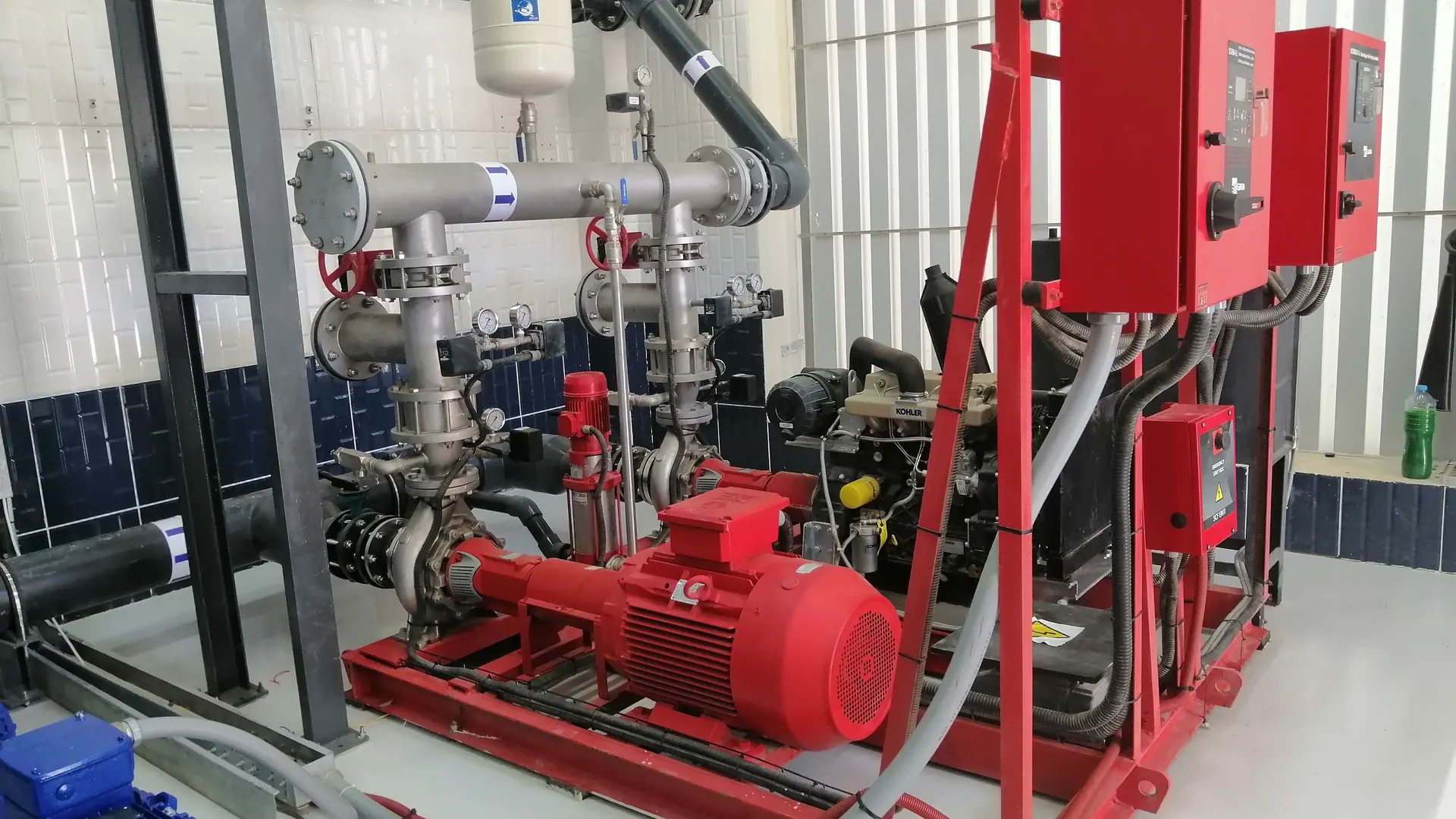
A fire pump should not be selected by choosing a familiar GPM rating and then trying to make the system fit it. The correct starting point is the hydraulic demand of the fire protection system: the required flow and the pressure that must still be available at the hydraulically most demanding point.
This practical guide explains the engineering workflow used to size a centrifugal fire pump and then verify that the selected pump can satisfy the system throughout its operating range.
When is a fire pump required?
A fire pump is used when the available water supply cannot provide the flow and pressure required by the fire protection system. The pump does not create the system demand; it adds the pressure needed to bridge the gap between the available water supply and the calculated demand.
Step 1: Determine the governing fire protection demand
Start with the hydraulic calculations for every system that the pump may be required to supply. Depending on the project, this can include automatic sprinklers, standpipes, hydrants, water spray or other water-based systems.
The governing case is not automatically the system with the largest flow. It is the case that produces the most demanding combination of flow and pressure at the pump.
Important: do not add unrelated system flows unless the applicable design criteria require those systems to operate simultaneously.
Step 2: Determine the required pump flow
The required pump flow is based on the governing hydraulic demand. The selected rated capacity should be a standard listed fire-pump rating that can satisfy that demand while the actual operating point remains on an acceptable part of the manufacturer’s certified pump curve.
A pump can operate above its rated flow; this is why the full curve matters. NFPA fire-pump acceptance testing evaluates the pump at no-flow, rated flow and peak flow conditions, with 150% of rated capacity being an important verification point when the available water supply permits it.
Step 3: Calculate the pressure required at the pump discharge
The discharge pressure must be high enough to overcome all pressure requirements between the pump and the remote design point. A useful engineering form is:
Required discharge pressure = required residual pressure + elevation head + friction/minor losses.
If a reliable positive pressure is available at the pump suction, the net pressure increase required from the pump can be reduced accordingly. The actual calculation must use the design suction condition, not an optimistic static reading.
Elevation pressure
For water, approximately 2.31 ft of elevation equals 1 psi, or about 10.2 m equals 1 bar. In high-rise systems, elevation can therefore become one of the largest components of the required pump pressure.
Friction losses
Include the calculated losses through pipe, fittings, valves, backflow devices and other components between the pump and the design point. These losses depend strongly on flow, so they must come from the hydraulic calculation rather than from a fixed percentage allowance.
Step 4: Plot the required duty point
Once flow and pressure are known, plot the required operating point against the proposed manufacturer’s fire-pump curve. Do not select the pump from the nameplate rating alone.
The curve review should include:
- the pressure available at the calculated system demand;
- the rated flow and rated pressure;
- the no-flow or churn pressure;
- the pump performance toward 150% of rated flow;
- the suction pressure expected at each relevant operating condition; and
- the maximum system pressure that can occur.
Step 5: Check churn pressure and maximum system pressure
Oversizing pressure can be as problematic as undersizing it. At no flow, a centrifugal fire pump normally develops more pressure than at its rated point. The designer therefore needs to check the maximum discharge pressure against the pressure ratings of the system components and determine whether pressure-control measures are required.
Step 6: Verify the 150% operating region
The peak-flow point is not a shortcut for sizing the system demand. It is part of verifying the pump’s performance range. NFPA acceptance-test provisions include operation at rated and peak loads, and where the water supply cannot support 150% of rated flow, the standard provides an alternative test based on rated flow or the maximum system demand/available flow as applicable.
Worked example
Assume a project hydraulic calculation produces a governing demand of 850 gpm. At that flow, the remote system requires 65 psi. The calculated elevation and network losses between the pump discharge and the remote point total 55 psi.
The required pump discharge pressure is therefore approximately:
65 + 55 = 120 psi.
If the design suction pressure available at the pump is 20 psi, the pump must add approximately:
120 − 20 = 100 psi net pressure.
The engineer would then evaluate an appropriate listed standard pump rating and its certified curve to confirm that the pump can deliver at least 850 gpm at the required net pressure, while also checking churn pressure, peak-flow performance, driver loading and the pressure limits of the system.
SESCO Engineering Note: choosing “1,000 gpm at 100 psi” simply because those numbers look close is not the final selection. The actual certified curve, suction condition and maximum system pressure must all be checked before the pump is approved.
Common fire pump sizing mistakes
- Selecting the pump before completing the hydraulic calculation.
- Using the largest flow without checking which scenario requires the highest pump duty.
- Ignoring available suction pressure or using an unrealistic suction condition.
- Adding an arbitrary safety percentage to flow and pressure and unintentionally oversizing the pump.
- Checking only the rated point and ignoring churn and high-flow performance.
- Ignoring component pressure ratings at maximum pump discharge pressure.
- Treating the 150% test point as the required design flow.
What information should be sent to the fire pump supplier?
- required system flow and pressure;
- design suction pressure and water-source information;
- preferred or required pump type;
- electric motor or diesel-engine driver requirements;
- electrical supply data where applicable;
- listing/approval requirements such as UL and FM;
- site elevation and ambient conditions where relevant; and
- project/AHJ requirements.
NFPA standards involved
NFPA 20 governs the installation and performance requirements for stationary fire pumps. The system demand itself comes from the standard governing the protected system, such as NFPA 13 for sprinkler systems or NFPA 14 for standpipe systems. Inspection, testing and maintenance after installation are addressed by NFPA 25.
Need help selecting a fire pump?
SESCO designs, supplies and assembles complete fire pump stations for commercial and industrial fire-protection projects. See our fire pump services or contact our engineering team with your hydraulic demand and project requirements.
This article provides general engineering guidance. Final fire-pump selection must be based on the project hydraulic calculations, the applicable code edition, manufacturer data and the requirements of the authority having jurisdiction.